Instruments
Passive Microwave
Geometry
The Geometry Module is in charge of simulating the spacecraft orbit and attitude, as well as the generation of the observation geometry of each instrument.
There are four different types of scenes:
- Earth pointing scenes: Following the SEPS (SMOS End-to-end Performance Simulator) example, Earth’s surface targets is classified as: land (bare soil, vegetated soil, snow covered, inland water bodies…), and ocean (roughed sea, iced sea) , and all them is affected by atmospheric and ionospheric effects. Note: in general atmospheric effects increase with frequency, while ionospheric effects decrease with increasing frequency, and are only noticeable at low microwave frequencies. Depending on the frequency and the required accuracy they could be neglected or not.
- Sky pointing scenes: These scenes are used for calibration purposes, either by turning the satellite upside down and making the instrument point to the zenith direction, of by switching the Earth-looking antenna and the “sky-horn”, as it is done in the microwave radiometers accompanying the radar altimeters. Sky scenes should take into account the cosmic background (2.725 K), the galactic radiation, and the Sun and the Moon (whenever applicable).
- Limb pointing scenes: These scenes are generated by defining the atmospheric characteristics and can also include a reference background spectrum (e.g., cosmic background, galactic radiation, Sun, or Moon when applicable). For limb sounders, special care must be taken when modelling the atmospheric emission (see for example).
- Other scenes: A way to calibrate small radiometer drifts and/or cross-correlate different instruments consists of comparing the brightness temperature histograms and forcing the minimum value to be the same for all (vicarious calibration). This is a particular case of the Earth pointing scenes over regions that are known to provide the coolest places on Earth in term of TB.
The Geometry Module is in charge of simulating the spacecraft orbit and attitude, the instrument line-of-sight, the observation area and the auxiliary geometrical data to feed the Scene Generator, like the footprint size, orientation, and local incidence angle.
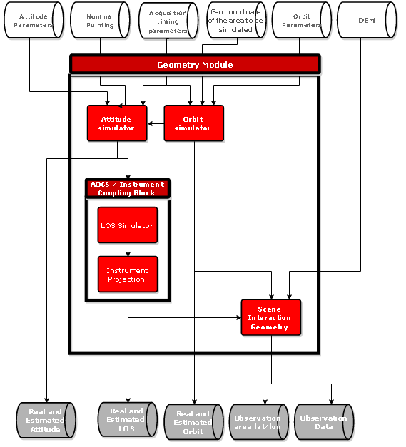
The Geometry Module, and the interaction between its Blocks, is shown in the following diagram:
Biblos.COTS This is Biblos COTS package with installation script. Script installs libraries:- kissFFT- boost- netcdf- zlib- hdf5- eigen
Biblos.Geometry This is a module composed of Biblos.Orbit, Biblos.Attitude, Biblos.AocsInstrumentCoupling and Biblos.SceneInteraction blocks.The Geometry Module is in charge of simulating the spacecraft orbit and attitude, the instrument line-of-sight, the observation area and the auxiliary geometrical data to feed the Scene Generator. The Orbit Block calculates the nominal, Satellite and Restituted orbit.• The Attitude Block calculates the nominal, Satellite and Restituted attitude.• The AOCS/Instrument Block simulates the detector line. It is composed by two sub-Blocks:o The LOS Simulator calculates the detector elements’ line-of-sight, and the misalignments in in instrument frame.o The Instrument Projection transforms the line-of-sight for the detector elements in ECEF frame.• The Scene Interaction Geometry Block calculates the area of observation from the detector line-of-sight in the digital elevation model DEM. This Block also calculates a number of geometrical inputs needed for the Scene Generation Module like the Observation Zenith Angle, Sun Zenith Angle, etc.
Biblos.Commons This is a package common for all the Blocks and Modules. Commons contain helper functions e.g. for reading NetCDF or parsing XML files as well as Blocks and Modules interfaces.
Tool: Tiff to NetCDF converter BIBLOS works with NetCDF format for the images. This is a tool to convert Tiff to NetCDF. It is external to BIBLOS, the user shall convert the image offline. THe package includes an executable, a README file (with instructions) and an example auxiliary file.
Biblos.Orbit In charge of the simulation of the nominal, real and estimated orbits. This block computes the nominal orbit from the input orbit parameters and disturbs this orbit with natural orbit perturbations. In addition, estimated orbit is calculated based on standard orbit determination methods.
Biblos.Attitude In charge of the simulation of the nominal, real and estimated platform attitude. This block computes the nominal attitude from the input mission configuration parameters and simulates the operation of attitude actuators, sensors and environmental torques.
Biblos.AOCSInstrumentCoupling This block is in charge of modelling the instrument LOS and detector projection coupling it with the platform AOCS and producing the final instrument viewing directions for image acquisition.Calculates the LOS (Line-Of-Sight) in instrument frame. The Instrument Projection calculates the LOS in ECEF frame. It is in charge of reproducing the scanning and pointing of the instrument LOS as function of time (cross-track, along-track, bidirectional, slowdown, limb…). In addition, this block couples the platform attitude with this scanning motion of the instrument.